the Creative Commons Attribution 4.0 License.
the Creative Commons Attribution 4.0 License.
 | 29 Oct 2025
Hand-operated fully reproducible static blade core opening bench
Raphaël Gallet
Fabien Arnaud
The EDYTEM Manual Core Opening Bench (MCOB) is a manually operated tool designed for opening soft sediment cores. This reproducible device was inspired by several existing, but as yet unpublished, models and was developed to ensure clean and precise cuts without contamination from plastic debris. The system comprises six technical components (frame, guiding system, sled, drive mechanism, core holding system, and cutting tools) and can accommodate cores of various diameters. Its hand-operated design enhances both safety and portability. All technical drawings, parts lists, and assembly guides are freely available via a GitHub repository, enabling the scientific community to reproduce and enhance the device.
- Article
(1996 KB) - Full-text XML
- BibTeX
- EndNote


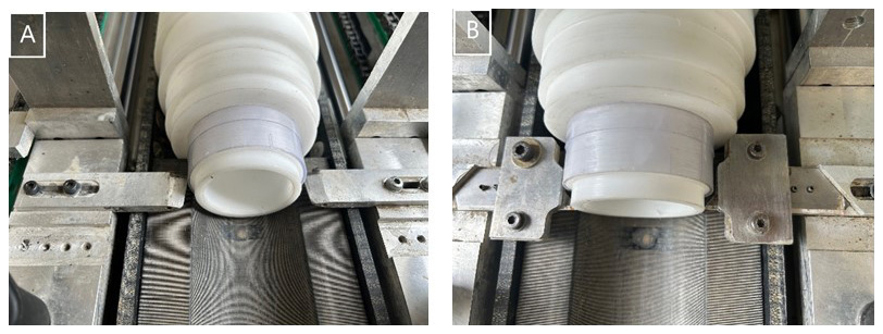
Every year, thousands of scientific papers dealing with sediment cores are published. For example, in 2024, Web of Science contained at least 1587 articles with the term “sediment core” in the title or abstract. All of these studies required sediments to be recovered in the field, typically in the form of a sediment-filled plastic barrel. In order to study the stratigraphy of these specific samples, the plastic liner must be cut along its longitudinal axis to “open” the core. Core opening is thus the foundation of thousands of studies. However, only two scientific publications describing a core opening device have been found since 1969 (Langford et al., 1969; Rogers et al., 2015). While some private companies commercialize certain models, most research laboratories have developed their own homemade devices based on commercial craft machines. Consequently, the method of opening is rarely described in scientific literature. Nevertheless, the method of opening used may affect the quality of the sediment surface and of subsequent samples studied. Among the features that should be avoided, irregular longitudinal cuts and asymmetric cuts in two halves are the most common. Historically, cores were often opened using circular rotating blades (Langford et al., 1969). While this technique is fast and efficient, it produces a lot of plastic shards, which may eventually contaminate the sample (Fig. 1). Using vibrating blades greatly mitigates this issue. However, static blades mounted on a sled that slides along a rigid frame seem to meet the requirements both for regular cutting and for preventing sample contamination by plastic shards, as discussed and demonstrated in Ohlendorf et al. (2011). Such devices exist in several European research laboratories, but, unfortunately, their designs have not been published, so they cannot be reproduced. In this paper, we present a homemade version of a static blade core opener that we call the EDYTEM Manual Core Opening Bench (MCOB), along with links to the plans for custom-machined parts and 3D-printed parts, a list of necessary commercial parts, and an assembly guide, so that the scientific community can reproduce it.
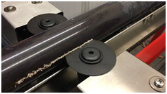
Figure 1Most common core opening features threatening the quality of studied sediment cores.
The idea for a new core opener project emerged at the EDYTEM lab following a dramatic increase in our core handling and core logging activities over the last 10 years. Our workflow requires us to handle cores of various diameters, with 63 and 90 mm being the most common, and lengths of up to 160 cm. The liners we typically use have a wall thickness of 2.1 mm. The core opener is therefore optimized to cut these polyvinyl chloride (PVC) liners into two equal parts simultaneously. However, the presented device only cuts the liner. The sediment must be separated by another process. Further developments are possible to modify the specifications, particularly with regard to diameters and wall thickness. The cutting of liners other than PVC has not been tested. For safety reasons, we also aimed to avoid electric-powered devices, as the presence of electric motors would necessitate stricter safety regulations. This design choice also facilitates easier transport of the device to the field, if necessary. The 3D-CAD parts were produced in the laboratory using an Ultimaker3 3D printer. The price of the supplies is around EUR 3000, but this needs to be re-evaluated due to recent inflation and does not take into account the time spent on development, assembly, adjustments, and/or tooling tests.
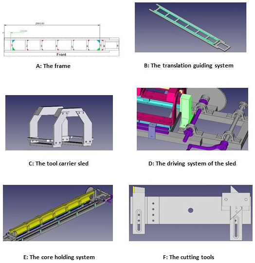
As mentioned above, the EDYTEM MCOB was inspired by an existing version of a static blade core opener (Ohlendorf et al., 2011). However, several months of trial and error were required to fine-tune the parts and identify the most functional technical choices. The complete device can be divided into six distinct parts to describe these choices (Fig. 2):
-
the frame (Fig. 2A), which serves as the rigid base of the entire device;
-
the translation guiding system (Fig. 2B), which ensures the linear displacement of the cutting tool over 180 cm;
-
the tool carrier sled (Fig. 2C), which is mounted on the translation system and hosts the cutting tools;
-
the driving system of the sled (Fig. 2D), which ensures its linear movement along the guiding system;
-
the core holding system (Fig. 2E), which keeps the core immobile during opening operations;
-
the cutting tools (Fig. 2F), which are mounted on the tool carrier sled and must be exchangeable to accommodate various diameters.
These parts were designed and mechanically developed using FreeCAD 0.18. Current versions of the numerical plans, a labelled list of components, an assembly guide, and a glossary of terms are available as a GitHub repository (Gallet and Arnaud, 2023).
3.1 Frame
The frame is constructed from 40 × 40 mm aluminium slot profiles featuring B8-type 8 mm channels, which are assembled using dedicated screwed T-nuts. Aluminium brackets were used to increase rigidity at each junction.
3.2 Guiding system
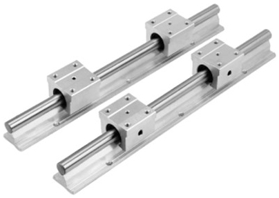
The guiding system uses a commercial model SBR20 × 2000 mm linear rail shaft (Fig. 3) which has four square ball-bearing square guiding blocks. It needs to be drilled in order to be mounted on the frame using T-nuts. Short-headed screws are required to allow free passage for the guiding blocks.
3.3 Tool carrier sled
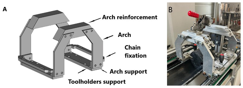
The tool carriage sled is an assembly of 18 machined parts (Fig. 4A) bolted together. It is directly connected to the side chains, which enable the system to move back and forth (Fig. 4B).
3.4 Driving system
The sled drive system is probably the part that is subject to the greatest mechanical stress. Indeed, a torque of 6.5 Nm must be applied to the crank handle in order to operate the core opener. Therefore, we opted for a gear-reduced double-chain translation system. The chains are standard 06B1 type. The sprockets are mounted on two 20 mm diameter shafts. One shaft has a 21-tooth sprocket and a manual crank, and the other has a 76-tooth sprocket which provides a mechanical advantage that multiplies the operator's input by approximately 3.6 (Fig. 5A). Strength is transmitted to two other sprockets which make the chain move. The sprocket, crank, and axis are bound together with mechanimbus-type pins (Fig. 5B). All elements were purchased from commercial sites.
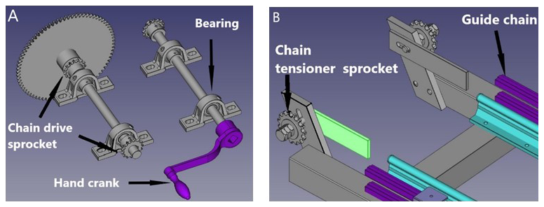
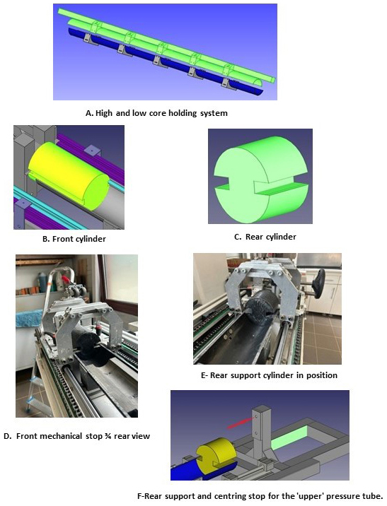
Figure 6(A) High and low core holding system, (B) front cylinder, (C) rear cylinder, (D) front mechanical stop rear view, (E) rear support cylinder, (F) rear support and centring stop.
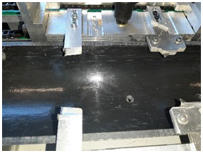
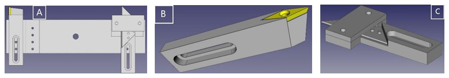
Figure 8Tool carrier with it tools (A), insert holder (B), cutting blade holder, (C) and 3D-CAD.
3.5 Core holding system
The core holding system is another complex subsystem that requires fine-tuning. It consists of two components (Fig. 6A):
-
Lower core holding system: an HDPE half-tube positioned at the bottom and cut 8 mm below the half-diameter. Adjustment wedges enable the insertion of cores of various diameters. This half-tube is mounted to the frame using five 3D-printed supports.
-
Upper core holding system: located at the top, this similar system consists of a half-tube (also cut 8 mm below the half-diameter) and adapters. It is used to press the core in order to prevent it from deformation, sliding, and/or rotation during the cutting. It is mounted on an aluminium profile of the same type as that used for the main frame. The upper system is installed after the core has been placed and is removed once the operation is complete.
The gap between these two assemblies is maintained by two cylinders positioned at either end. At the front (Fig. 6B and D), the plastic cylinder (3D-printed in PLA) blocks the core and prevents it from sliding due to the forces exerted by the cutting tools on its plastic walls. It also maintains the gap between the two half-tubes (Fig. 6D and E). At the rear, a shorter cylinder ensures that the gap is maintained during the cutting. Two wide and deep grooves are required on both cylinders to allow unobstructed passage for the cutting tools at the beginning and end of the stroke.
These two cylinders are complemented by two static assemblies. At the front end, three vertical profiles are glued together: two taller profiles and a central profile whose height is slightly less than the diameter of the front cylinder. The upper profile of the upper core holding system, which supports the upper half-tube, is guided by the two taller profiles. The shorter central profile enables the upper half-tube to lie on the front cylinder.
At the rear end, the mechanical stop consists of a simple vertical aluminium profile that holds a 3D-printed plastic component (the rear mechanical stop Fig. 6F), which receives a centring pin, located at the back of the upper core holding assembly. Once the centring pin is inserted into its hole, this component is adjusted so that slight pressure is applied to the rear cylinder.
This system is completed by the addition of two clamping devices: one is fixed at the front end, and the other is movable and mounted on the tool carrier sled (Step 5 of Figure 10).
3.6 Cutting tools
The system is optimized for liners with external diameters of 63 and 90 mm and a wall thickness of 2.1 mm, which is the average measured thickness of the most commonly used liners. The selected solution involves two tool carrier assemblies positioned one on either side of the core opener (Fig. 7), allowing simultaneous cutting on both sides. After multiple trials, the final configuration includes the following on each side:
-
The first tool to engage the liner is a CoroTurn® 107 carbide insert (Sandvik-VCGX 110204-A) for machining plastic and aluminium, mounted on a custom-made aluminium holder. This tool is configured to make a 0.5 mm deep V-shaped incision to guide the second tool (Fig. 8B);
-
The second tool is a commercial cutting blade (Fig. 8C), which is placed behind the first tool (Fig. 8A). This blade follows the groove created by the first tool in order to cut through the PVC. Two distinct tool sets have been designed to facilitate the switching of the core opener for different liner diameters. For each setup, an adjustment tool is used to fine-tune the position of the cutting tools.
This opening bench has been designed and optimized for use with 2.1 mm thick transparent PVC liners with outside diameters of 63 and 90 mm, as used in the EDYTEM laboratory. Changes to the diameter are made by adjusting the shims and adjusting the cutting tools (Fig. 9).
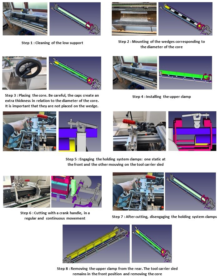
Steps 1–8 (Fig. 10) show a series of photographs of the complete core opening workflow. An operating manual is also available in Git format.
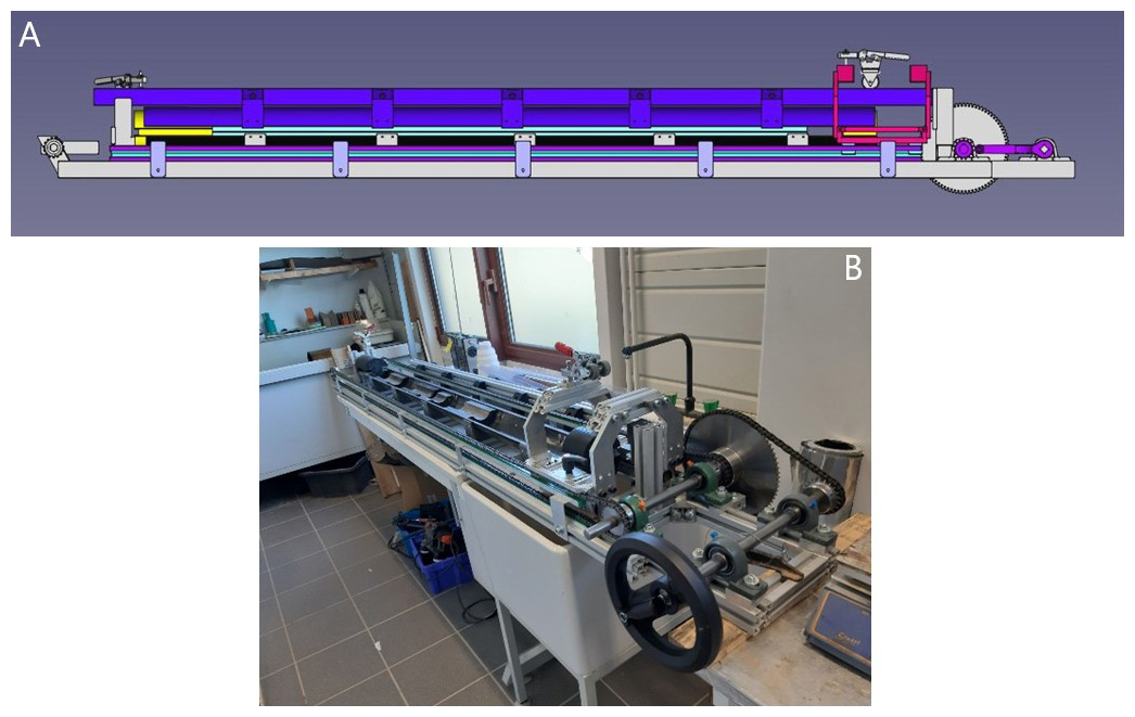
The EDYTEM-MCOB core opener is a reliable, cost-effective, and fully reproducible solution for processing sediment cores. This manually operated cutting system ensures precise, linear cuts while minimizing the risk of sample contamination. After more than 1 year of use at EDYTEM (Fig. 11), both by laboratory staff and external users, the system has proven to be efficient and robust, requiring only minor sled alignment adjustments. The only interventions needed are regular replacement and adjustment of parts according to the diameter of the sediment core.
All the information needed to recreate our MCOB can be found online under a Creative Commons BY 4.0 licence (https://doi.org/10.48579/PRO/AFXQRN; Gallet and Arnaud, 2023). We encourage researchers and engineers to adopt, adapt, and improve this device and to share their advancements with the scientific community. The authors would be grateful if users cited the present paper in subsequent publications using cores opened with this device.
FA initiated the development of a simple and practical tool for cutting sediment core tubes, defining the list of requirements and technical specifications. FA participated in testing and technical decision-making and assisted RG in writing the article.
RG designed and built several prototypes, testing them in collaboration with EDYTEM lab members. Once validated, RG compiled all the information needed to reproduce the bench, wrote the instructions, edited the technical plans, and made all these data available on DataIndores.
The contact author has declared that neither of the authors has any competing interests.
Publisher's note: Copernicus Publications remains neutral with regard to jurisdictional claims made in the text, published maps, institutional affiliations, or any other geographical representation in this paper. While Copernicus Publications makes every effort to include appropriate place names, the final responsibility lies with the authors. Views expressed in the text are those of the authors and do not necessarily reflect the views of the publisher.
This paper was edited by Thomas Wiersberg and reviewed by Christian Ohlendorf and one anonymous referee.
Gallet, R. and Arnaud, F.: Sediment core opener: Assembly instructions and plans, V2, data.InDoRES [data set], https://doi.org/10.48579/PRO/AFXQRN, 2023.
Langford, A., McDougall, J. C., and Robertson, N.: A new large-diameter piston corer and core-liner cutter, New Zealand Journal of Marine and Freshwater Research, 3, 595–601, https://doi.org/10.1080/00288330.1969.9515321, 1969.
Ohlendorf, C., Gebhardt, C., Hahn, A., Kliem, P., and Zolitschka, B.: The PASADO core processing strategy – A proposed new protocol for sediment core treatment in multidisciplinary lake drilling projects, Sedimentary Geology, 239, 104–115, https://doi.org/10.1016/j.sedgeo.2011.06.007, 2011.
Rogers, G. N. D., Bonner, K. I., Wood, J. R., and Wilmshurst, J. M.: The rail-cutter: a simple, cheap and compact system for opening sediment cores in the lab and field, J. Paleolimnol., 53, 433–436, https://doi.org/10.1007/s10933-015-9830-x, 2015.