Articles | Volume 32
https://doi.org/10.5194/sd-32-55-2023
Technical development
 | 
26 Oct 2023
Technical development |  | 26 Oct 2023

Poor Man's Line Scan – a simple tool for the acquisition of high-resolution, undistorted drill core photos

Lukas Gegg and Johann Gegg
Abstract

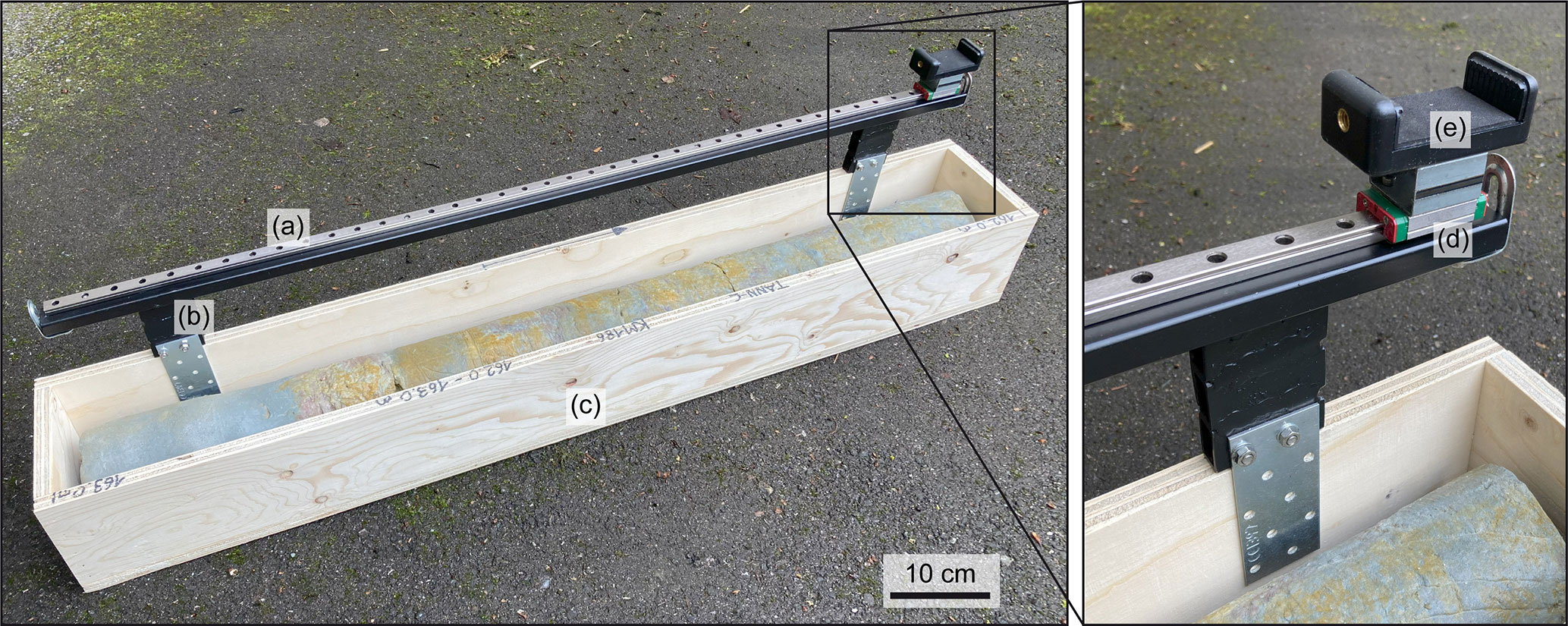
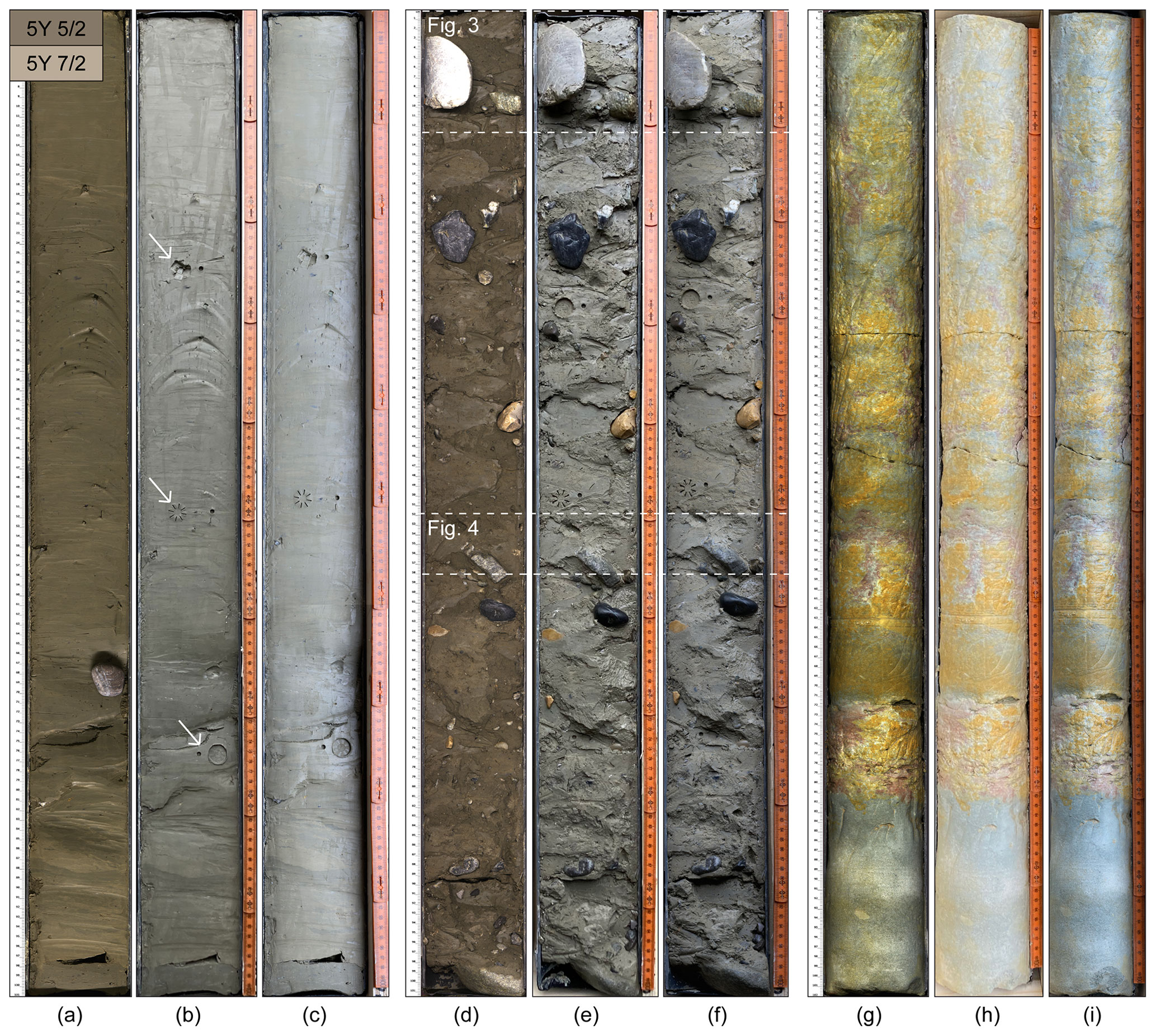
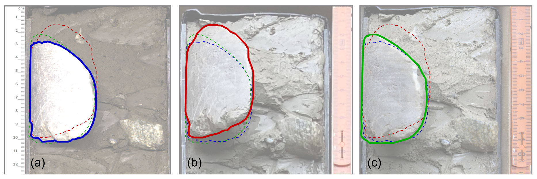
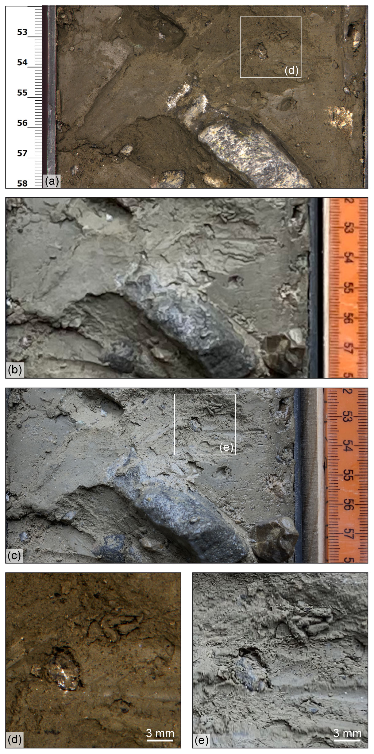
The analysis and presentation of drill cores, an essential part of geoscientific research, requires the acquisition of high-quality core photos. Typically, core photos are either taken by hand, which often results in poor and inconsistent image quality and perspective distortions, or with large, heavy, and thus inflexible as well as expensive line scan setups. We present a simple, portable “Poor Man's Line Scan” setup that turns a customary smartphone into a semi-automatic core scanner utilising its panoramic photo function while guided on a rail in order to record undistorted core photographs at high resolution. The resulting images, although affected by some minor artefacts, are clearly superior in quality and resolution to single photos taken by hand and are comparable to images taken with commercial line scan cameras. The low cost ( EUR 100) and high flexibility, including the potential for modifications, of our tool make it an interesting alternative to the classical line scan setup.

Dates
1 Introduction

Drill cores recovered from commercial or scientific boreholes are one of the most important tools in geoscientific research but also in applied fields of work such as ground investigation. For the detailed description, presentation, and interpretation of drill cores, high-quality core photos are essential (Ettensohn, 1994; Dolgiy et al., 2015). In addition, employing state-of-the-art techniques, core photos can allow further analyses such as automated grain size (Tran et al., 2022) or lithological classification (Fu et al., 2022). However, the dimensions of drill cores, which are typically 5–20 cm in diameter and 1 or several metres long, make the acquisition of suitable images challenging.

Whole-core photographs taken from a distance with a handheld camera often lack detail and are affected by perspective distortions but can be improved by sophisticated imaging setups (e.g. USBR, 1998). The best results are achieved by line scan imaging, where an electric motor moves a drill core past a fixed camera acquiring sequential images that are subsequently automatically stitched together, resulting in a full core photo (e.g. Geotek Limited, 2017). However, such setups are not only expensive but also large, heavy, and thus stationary.

Fortunately, current smartphones equipped with a panoramic photo mode are capable of the same image-stitching process that is used in classical line scan imaging (Altaratz and Frosh, 2021). We present a simple and inexpensive ( EUR 100, excluding phone) setup we refer to as “Poor Man's Line Scan” (PML) that turns a customary smartphone into a semi-automatic core scanner capable of acquiring high-resolution, undistorted, top–down, i.e. non-unrolled, bisected and whole-round drill core images. Moreover, being portable, the PML can readily be taken into the field, to construction sites, or to core repositories.

https://sd.copernicus.org/articles/32/55/2023/sd-32-55-2023-f01

Figure 1The “Poor Man's Line Scan” setup for core photo acquisition. It consists of a guide rail (a) bolted to a steel frame (b) that can be attached to a wooden core box (c). A ball-bearing-mounted slide block (d) moves a smartphone attached with a phone clamp (e) along the rail in order to acquire a continuous image in panoramic picture mode.

Download

2 Setup and procedure

The PML setup consists of a 1 m long track, over which a smartphone, in our case an Apple® iPhone SE 2020, is guided along a drill core at a fixed distance of  15 cm in order to acquire a scan image in panoramic picture mode, with a width / height ratio of > 4 and with the drill core in question being recorded in great detail. As the track, we selected an MGN12H (12 mm wide) linear guide rail that is commonly used, for example, in 3D printing (Fig. 1). This rail is bolted to a square steel frame with a U-shaped seating that allows placing it on the sidewall of a typical wooden drill core box, to which a tape measure is attached for scale. A spring-loaded phone clamp is fitted to a ball-bearing-mounted block that slides over the rail with minimal play. With the smartphone clamped to the slide block and auto-focused on one of the core ends, the panoramic photo acquisition is started, and the phone is guided along the core by hand in order to acquire a coherent scan image. Inconsistencies in acquisition speed are accounted and corrected for by the phone software, and a warning message notifies users if the scanning is done too rapidly. For ideal results, we recommend photographing in naturally or artificially well-lit surroundings but without direct light on the drill core in order to avoid hard cast shadows. Shadows from the core box can be avoided by propping a bisected core up on its other half, so that the surface to be imaged is level with the box edge. To ensure the comparability of different images, we further recommend attaching a colour correction card to the drill core or core box, allowing for appropriate image editing afterwards.

The photos presented in the following were taken from selected cores of the International Continental Scientific Drilling Program (ICDP) borehole 5068_1_C in Tannwald, southern Germany (Anselmetti et al., 2022). Line scan photos were recorded with a Geotek Core Imaging System (Geotek Limited, 2017) in the laboratory of the University of Bern. Further images were taken in daylight with the iPhone SE 2020 and the PML setup as shown in Fig. 1 and, for comparison, with the same smartphone camera held by hand from a distance. The length of the PML scan image is restricted by the capabilities of the smartphone available (i.e. the maximum width of a panoramic picture). Here, 1 m core sections had to be imaged on two separate photos and later stitched together manually using the freeware GIMP (GNU Image Manipulation Program). Apart from that, the smartphone photos were not edited (e.g. contrast enhancement or colour correction).

3 Results

The aspect ratios of a photographed core are identical for all three imaging approaches (Fig. 2a–c: width / length = 1 / 9.5). However, while core photos taken with a handheld camera suffer from major perspective distortions, especially near the core ends, those acquired with the PML are significantly truer to the original (Fig. 3). With the presented setup, we acquired scan images with a resolution of  250 px per core centimetre, which is comparable to classical line scan images, and enable users to zoom in on small-scale details such as individual clasts (Fig. 4). The manual stitching-together of individual images – here two per 1 m core section – takes a few minutes at a time and on some occasions resulted in a minor artefact in the image centre. Other minor artefacts may result from vibrations during photo acquisition (Fig. 5).

https://sd.copernicus.org/articles/32/55/2023/sd-32-55-2023-f02

Figure 2Comparison of photos of different drill cores (10 cm diameter, 1 m length) from ICDP borehole 5068_1_C (Anselmetti et al., 2022), taken with different imaging setups. (a–c) Pleistocene glaciolacustrine fines; bisected drill core with a mostly smooth surface. (d–f) Pleistocene glacial diamicts; bisected core with a very irregular surface. (g–i) Oligocene to Miocene siltstone and sandstone; whole-round core. Panels (a), (d), and (g) were taken with a classic Geotek line scan camera setup and artificial lighting in the laboratory in December 2022 (© Bennet Schuster, University of Freiburg and University of Bern); panels (b), (e), and (h) with a customary smartphone camera (Apple® iPhone SE 2020) from a distance; and panels (c), (f), and (i) with the same phone camera using the PML setup, the latter both in daylight in May 2023. Differences in colour appearance are mainly attributed to artificial vs. natural lighting, and some colour change may have also occurred during storage after bisecting. For reference, the Pleistocene deposits were, in comparison to a Munsell colour chart, classified as mainly yellowish grey (5Y 7/2) to light olive grey (5Y 5/2) directly after opening. The corresponding RGB colours after Centore (2013) are provided in the top left corner. Note: cores in panels (b) and (c) and in (e) and (f) have surficial marks from in situ geotechnical testing; see arrows in (b).

https://sd.copernicus.org/articles/32/55/2023/sd-32-55-2023-f03

Figure 3Comparison of the depiction of the large quartzite clast at the top of Fig. 2d–f, which sticks out several centimetres from the bisected core surface and therefore appears differently when photographed with different focal lengths. The Geotek line scan (a, © Bennet Schuster, University of Freiburg and University of Bern) as well as the PML (c) reproduce the clast shape true to the original, whereas it is visibly distorted in the photograph taken of the full core from a distance (b).

https://sd.copernicus.org/articles/32/55/2023/sd-32-55-2023-f04

Figure 4Detailed comparison of a selected interval from one of the drill cores presented in Fig. 2. Shown is a bisected core with an irregular surface resulting in high-contrast core photos. The same interval has been imaged with different setups: (a) line scan (© Bennet Schuster, University of Freiburg and University of Bern), (b) handheld phone camera from a distance, and (c) phone camera with the PML. Panels (d) and (e) show zoom-ins of (a) and (c), respectively.

https://sd.copernicus.org/articles/32/55/2023/sd-32-55-2023-f05

Figure 5Potential artefacts of core photos taken with the PML setup include (a) blurred bands as a result of vibrations during the panoramic picture acquisition (highlighted by dashed lines and zoomed inset) and (b) minor misfits and/or colour changes where two separate images are manually stitched together. Note: the latter could be improved if lens aperture and white balance of the phone camera could be adjusted manually.

Download

4 Assessment and conclusion

The comparison of different imaging techniques reveals that core photos taken individually with a handheld smartphone camera from a distance are suitable for low-resolution illustrative purposes where small-scale details are not relevant if the photos are taken meticulously to avoid distortions as much as possible (Fig. 2). For detailed imaging of entire drill cores, in order to archive or further analyse the sections, this is not adequate as the limited image resolution does not allow for sufficient magnification. Here, line scan images are clearly superior due to their high resolution and image fidelity (i.e. absence of perspective distortions). However, the comparison shows that scan images taken with our PML setup and a smartphone allow a similarly high degree of detail as well as image fidelity (Figs. 3, 4). The resolution of  250 px per core centimetre, corresponding to a pixel size of  40 µm, is in the same range as the Geotek Core Imaging System considered for comparison (Geotek Limited, 2017).

Thus, the results achieved with the presented core photography setup are compelling. The image quality achieved with our setup comes close to proper line scan images but at a fraction of the cost ( EUR 100 excluding phone) and, as a second major advantage, with the benefit of the flexibility of a portable setup. Therefore, it does not have to be set up stationarily in a core laboratory but can be easily transported and utilised for example at a drill site or a core repository. Furthermore, it is straightforward to use and requires only minimal training for the operator. Disadvantages of the PML include minor image artefacts that could not be entirely avoided (Fig. 5) as well as the inconvenience of transferring the acquired photos from the smartphone to the computer and of cropping and, if necessary, stitching individual photos together. In addition, the present setup depends on suitably well-lit surroundings and, especially if light conditions change over time, may require later manual image editing (e.g. contrast enhancement or colour correction; note: PML pictures are unedited in all figures). Like the Geotek line scan it is suitable only for top–down and not for unrolled core photos; however the out-of-the-box image-stitching capabilities of a smartphone might also be a suitable basis for an unrolled core imaging setup.

As presented here, the PML is a very simple tool, and further modifications can be made as desired. For instance, it might be more convenient to mount the guard rail on a tabletop rack instead of a core box. We suggest further that image quality can most likely be further enhanced by using a newer smartphone with a more sophisticated camera. Also, a multidirectional LED setup could be attached to the sliding block allowing for more consistent and, where appropriate, brighter lighting of the drill core. For wet or otherwise highly reflective core surfaces, an additional polarising filter might be helpful to reduce glare.

In summary, we argue that the PML tool may be an interesting alternative to an inflexible and costly conventional line scan setup, especially for working groups that only occasionally deal with drill cores. While it is introduced here in the context of drill core photography, it could of course also be applied in other fields of work that are concerned with objects of comparable length / width ratios.

Code and data availability

No code or data sets were used in this article.​​​​​​​

Author contributions

LG developed the concept and initial design of the PML, which was improved on by both authors before JG built the prototype. The paper and figures were drafted by LG and finalised by both authors.

Competing interests

The contact author has declared that none of the authors has any competing interests.

Disclaimer

Publisher’s note: Copernicus Publications remains neutral with regard to jurisdictional claims in published maps and institutional affiliations.

Acknowledgements

We thank Bennet Schuster (University of Freiburg and University of Bern) for providing access to and line scan images of the drill cores from Tannwald (ICDP 5068_1_C). We further thank Thomas Wiersberg for editorial handling, and Kristina Brady Shannon (University of Minnesota) and Henning Lorenz (University of Uppsala) for their constructive and thorough review of our manuscript.

Review statement

This paper was edited by Thomas Wiersberg and reviewed by Henning Lorenz and Kristina Brady Shannon.

References

Altaratz, D. and Frosh, P.: Sentient Photography: Image-Production and the Smartphone Camera, Photograph., 14, 243–264, https://doi.org/10.1080/17540763.2021.1877788, 2021.  

Anselmetti, F. S., Bavec, M., Crouzet, C., Fiebig, M., Gabriel, G., Preusser, F., Ravazzi, C., and DOVE scientific team​​​​​​​: Drilling Overdeepened Alpine Valleys (ICDP-DOVE): quantifying the age, extent, and environmental impact of Alpine glaciations, Sci. Dril., 31, 51–70, https://doi.org/10.5194/sd-31-51-2022, 2022. 

Centore, P.: Conversions between the Munsell and sRGB colour systems, https://www.munsellcolourscienceforpainters.com/ConversionsBetweenMunsellAndsRGBsystems.pdf (last access: 9 August 2023), 2013.​​​​​​​ 

Dolgiy, K., Belashev, B., and Gorkovets, V.: Automated drill core scanning, Int. J. Innov. Res. Eng. Managem., 2, 85–90, 2015. 

Ettensohn, F. R.: Development and Potential of Core-Logging Manuals, Geotech. Test. J., 17, 393–398, https://doi.org/10.1520/GTJ10114J, 1994. 

Fu, D., Su, C., Wang, W., and Yuan, R.: Deep learning based lithology classification of drill core images, Plos One, 17, e0270826, https://doi.org/10.1371/journal.pone.0270826, 2022. 

Geotek Limited: Geotek Core Imaging System (CIS): High resolution linescan photographs for immediate and archival core record applications, Geotek Limited, http://www.geotek.co.uk/wp-content/uploads/2017/06/MSCL-CIS.pdf (last access: 17 May 2023), 2017. 

Tran, T. T., Payenberg, T. H., Jian, F. X., Cole, S., and Barranco, I.: Deep convolutional neural networks for generating grain-size logs from core photographs, AAPG Bull., 106, 2259–2274, https://doi.org/10.1306/100212121019, 2022. 

USBR: Guidelines for Core Logging, USBR Engineering Geology Field Manual, 2nd edn., vol. I, United States Department of the Interior Bureau of Reclamation, 432 pp., 294–312, 1998. 

Download
Short summary
Geoscientists working with drill cores often struggle with proper photo documentation. We present a simple smartphone-based setup for acquiring high-resolution undistorted core pictures as an alternative to state-of-the-art commercial line scan imaging systems that are typically expensive and inflexible. It makes use of the phone's panoramic picture mode while being guided along the core in question on a rail, and the resulting images are of similar quality to classic line scan photos.